SUPERTECH PERFORMANCE
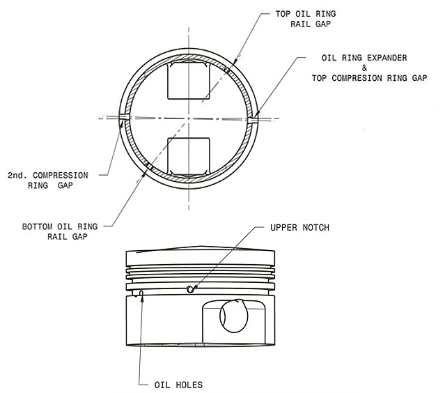
Piston and Ring Gap
Piston to cylinder wall clearance
Please read the specification sheet provided with your pistons. Piston diameter must be measured at the gauge point indicated in the diagram. Required clearance depends on diameter, alloy, type of forging (full skirt or slipper), application, operating conditions, etc.
Recommended Ring Gap
It is important to recognize that some end gaps for individual engines may vary from this standard because of engine manufacture’s requirements, type of application, fuels, etc. The top ring gap should be as small as possible to avoid blow-by. The table appearing below is for reference only.
Top Ring
Multiply the Bore diameter in inches by the following factor: (if diameter is in mm divide by 25.4 to convert into inches)
| Application | Factor |
|---|---|
| Street Performance | 0.0045 |
| Moderate Turbo/ Nitrous | 0.0050 |
| Drag / Oval track | 0.0055 |
| Turbo / Nitrous Race only | 0.0065 |
Second Ring
Multiply the First Ring Gap x 1.25
Oil Ring Gap
Minimum Gap 0.015”
Wire Locks installation
Insert one end of the lock into the groove and continue spiral feeding until de lock is fully seated.
Oil Ring installation
Example: Subaru Oil Ring with rotational locking detent
The Oil Ring Side Rail are supplied with one or two tabs: One is to lock the rail using one of the grooves in the piston and is installed with the tab facing the side of the groove. The other tab (if available) is to lock the middle expander. Use at the bottom or at the top (is the same).
- Install the middle expander with end gap about 90 degrees from the wrist pin centerline.
- Locate the upper notch in the oil ring groove. Install Lower Oil Ring Side Rail and rotate it until the tab falls in one of the oil grooves oposite to the upper notch.
- Install the Top Oil Ring Side Rail rail and rotate it until the tab falls in the upper